Descriptions, Schematics, Layouts, etc.
Last updated March, 2024This page is my attempt to correct the general lack of schematics and technical information about Hiwatt amplifiers. One hand-drawn set of schematics has been widely circulated, and published in both Pittman and Weber's books, and a few Audio Brothers schematics have been seen in the wild.
Each of these only captures a point in time, and as far as I know, no one has ever analyzed and documented the differences as the Hiwatt design evolved.
Because I frequently get asked about what tools I use to create these schematics, I have created a page here which tells the story.
The Circuits
Dave Reeves designed amps for Sound City before and while forming Hylight. It is very instructive to compare the early Sound City and Hiwatt circuits, as there are many similarities.
The early Hylight amps (<#1000) included a lot of different experiments, such as shared V1 cathodes and a cathode follower driving the tone stack.
From ~ 1000 on, there were only a few important circuit variations in the Hylight/Biacrown circuits, which were combined in distinct ways.
"Classic" Hiwatt Circuits
Input Stage Variations:
- The early input circuit version (Input 1) used a traditional resistive mixer to combine the two input channels. Half of V2 went unused.
- The later input circuit (Input 2), used both halves of V2 to do the input channel mixing.
- The OL and LEAD input circuits (Input 3) went back to the resistive mixer, and used the second half of V2 as an additional gain stage. These can be easily recognized by the "flying" components on the V2 socket.
Phase Inverter (PI) Variations:
- The earlier circuit (PI 1) used a cathode-follower directly connected to the PI circuit to both set the DC level and buffer the signal.
- The middle and later units (PI 2) capacitively coupled the last
preamp stage to the PI. The former cathode follower section now has its
input connected to a DC voltage divider, and is used strictly as a
low impedance voltage reference.
There is a thorough analysis of the unique Hiwatt fixed-bias PI by Richard Kuehnel here.
Combination I:
The earliest DRs with 4-inputs used Input 1 and PI 1. I've never seen a
schematic of this circuit, and I created this one by reverse engineering,
using detailed photos.
Combination II:
At some point, the circuit was changed to use Input 1 and PI 2 (this
version is represented by the Audio Bros and Hiwatt.com schematics). I
believe some 4-inputs were made this way (and certainly the reissues
were ;-).
Combination III:
Finally, the circuit was changed to use Input 2 and PI 2. This change was
definitely in all the 2-input heads, and is represented by the
widely-circulated freehand-drawn schematics in Pittman and elsewhere.
The OL Model (early 80's):
Biacrown's "high gain" model moved back to the Input 1 circuit (still
keeping PI 2), but used the "extra" half triode as an additional gain
stage.
The LEAD Model (early 80's):
This was basically the same as the OL model, but with an extra level
control after the extra gain stage, which was marked "Overdrive" on the
front panel,
Which sounds best? Haven't tried 'em all, but I suspect there's relatively little difference overall. It seems to me that the Hiwatt "sound" mostly comes from the unique TMB tone circuit and perhaps the unusual Presence circuit, which didn't really change. The Partridge transformers and the distinctive PI circuit contribute, but these did not change either. I think you'd be hard pressed to tell the difference in a double-blind test.
It was very interesting to me to note how much of the Hiwatt character was captured by DST Engineering's "MarWatt" design, with a Hiwatt-like input stage and TMB circuit, but using cathode-biased EL84 outputs, no presence or NFB, and a normal PI and iron. I never heard the ax84 "lowatt" design, but I'll bet this also captured a lot of the character.
I eventually did build one or these.
Note: Many of the diagrams below are available in both PDF and GIF form. In general, the former is better for printing and the latter is better for viewing.
Layouts
(Preamp tagboards are 1.75 x 11.75 inches)
- Early 70's four-input tagboard (GIF) Annotated version (functional labels for all parts)
- Mid 70's four-input tagboard (GIF)
- Late 70's two-input tagboard (GIF)
- Early 70's four-input preamp layout, rev 1.4 (PDF) (GIF)
- Mid 70's four-input preamp layout, rev 1.3 (PDF) (GIF)
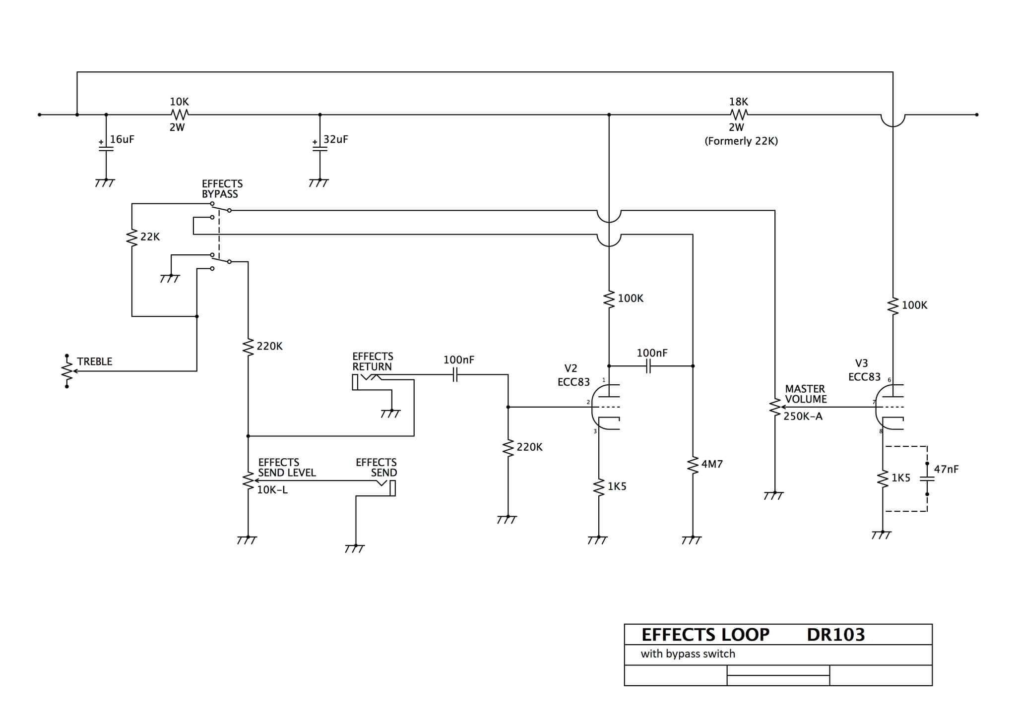
- 70's DR103 power amp layout, rev 1.2 (PDF) (GIF)
- 70's DR504 power amp layout, rev 1.1 (PDF) (GIF)
- Mid 70's DR201 power tagboard)
- Early 70's DR103 layout COMPLETE, rev 1.0 (PDF)
- Early 70's DR504 layout COMPLETE, rev 2 (PDF)
- Early 70's DR405 layout COMPLETE, rev 1.4 (PDF)
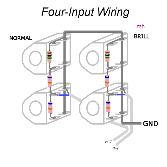
- Wiring diagram for the four input option (Another diagram)
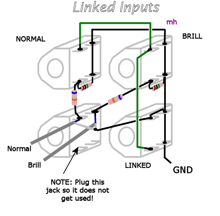
- Wiring diagram for the linked input option
My Schematics
PreampsUnusual Preamp VariantsNote: unless otherwise indicated,
- All resistors were 1/2 watt carbon film.
- All coupling capacitors were 400v polyester film-and-foil
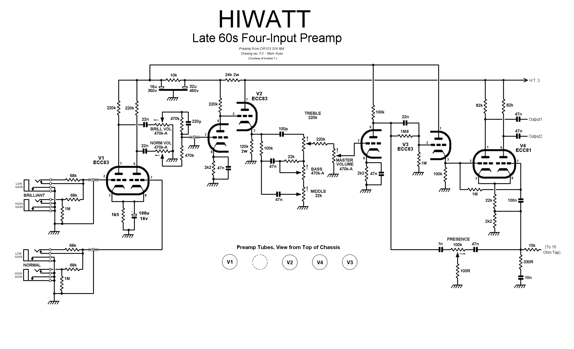
Late 60s Sound City/Hiwatt Preamp, rev 1.1 - This was a CP103 precursor. GIF Late 60s DR506 Bass Preamp, rev 1.0 GIF Late 60s Four-Input Preamp (I), rev 1.1 GIF Late 60s Four-Input Preamp (II), rev 1.1 GIF Early 70s Four-Input Preamp, rev 2.0 GIF Early 70s Linked-Input Preamp, rev 1.0 GIF Early 70s Linked-Input Preamp, rev 2.0 (courtesy of G.M.Flore) GIF Early 70s "The Ox" Preamp, rev 1.0a - J.E.'s CP103? GIF Mid 70s Four-Input Preamp, rev 1.4 GIF 70s Two-Input "Jimmy Page" Preamp, rev 2.3 GIF Late 70s Two-Input Preamp, rev 1.3 GIF Late 70s STA-Series Slave Preamp, rev 1.0 GIF Early 80s Two-Input "OL" Preamp, rev 1.0 GIF Early 80s Two-Input "SAP" Preamp, rev 1.0 GIF Early 80s Two-Input "LEAD" Preamp, rev 1.0 GIF Early 80s Four-Input DR405 Preamp, rev 1.1 GIF CP103 Preamp, rev 1.1 GIF Reissue CP103 Preamp, rev 1.1 GIF
Output Stages
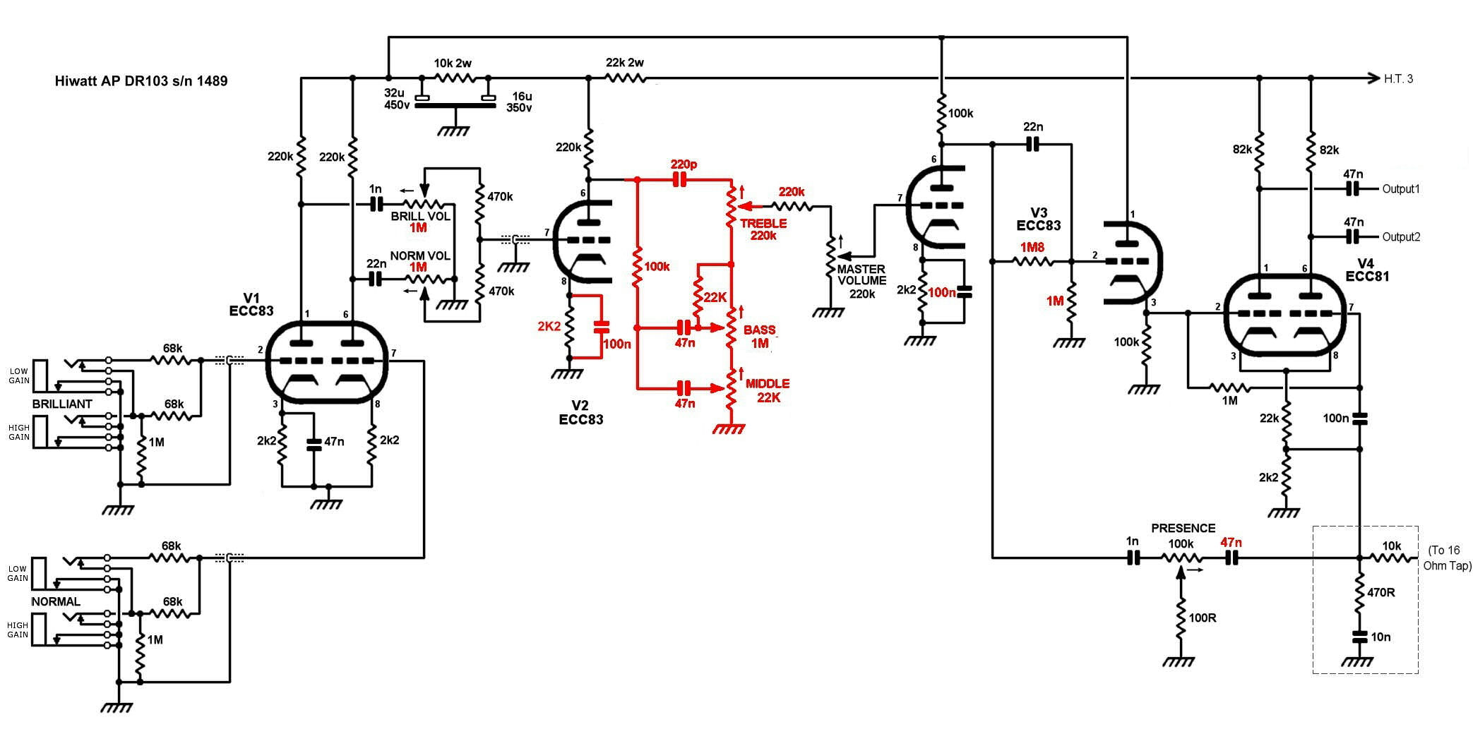
Hiwatt Preamp S/N 727 (courtesy of Stuart C.) JPG Hiwatt Preamp S/N 894 (courtesy of Andrew Y.) PNG Hiwatt Preamp S/N 903 (courtesy of Clayton C.) GIF Hiwatt Preamp S/N 1489 (courtesy of Stuart C.) JPG
Power Supplies
Late 60s DR506 50 Watt Output Stage, rev 1.0 GIF DR504-style 50 Watt Output Stage, rev 1.2 GIF DR103-style 100 Watt Output Stage, rev 1.1 GIF DR201-style 200 Watt Output Stage (6 x EL34 version) rev 1.3 GIF DR201-style 200 Watt Output Stage, (4 x KT88 version) rev 1.4 GIF DR405-style 400 Watt Output Stage, rev 1.4 GIF
Complete
DR506 (50 Watt) Power Supply, rev 1.0 GIF DR504-style (50 Watt) Power Supply, rev 1.1 GIF DR103-style (100 Watt) Power Supply, rev 1.3 GIF DR201-style (200 Watt) Power Supply, rev 1.4 GIF DR405-style (400 Watt) Power Supply, rev 1.2 GIF
Note: The revision numbers shown above are for the drawings, not the circuits.
- My DR504 OL (GIF)
Scanned Schematics
Audio Brothers
- DR 103 Manual (Complete) July 1994 (courtesy of Bob C.)
- DR103 Preamp Issue 4, 19/05/95, S/N AB0309 Onwards
- SA112 Preamp Issue 1, 18/07/94
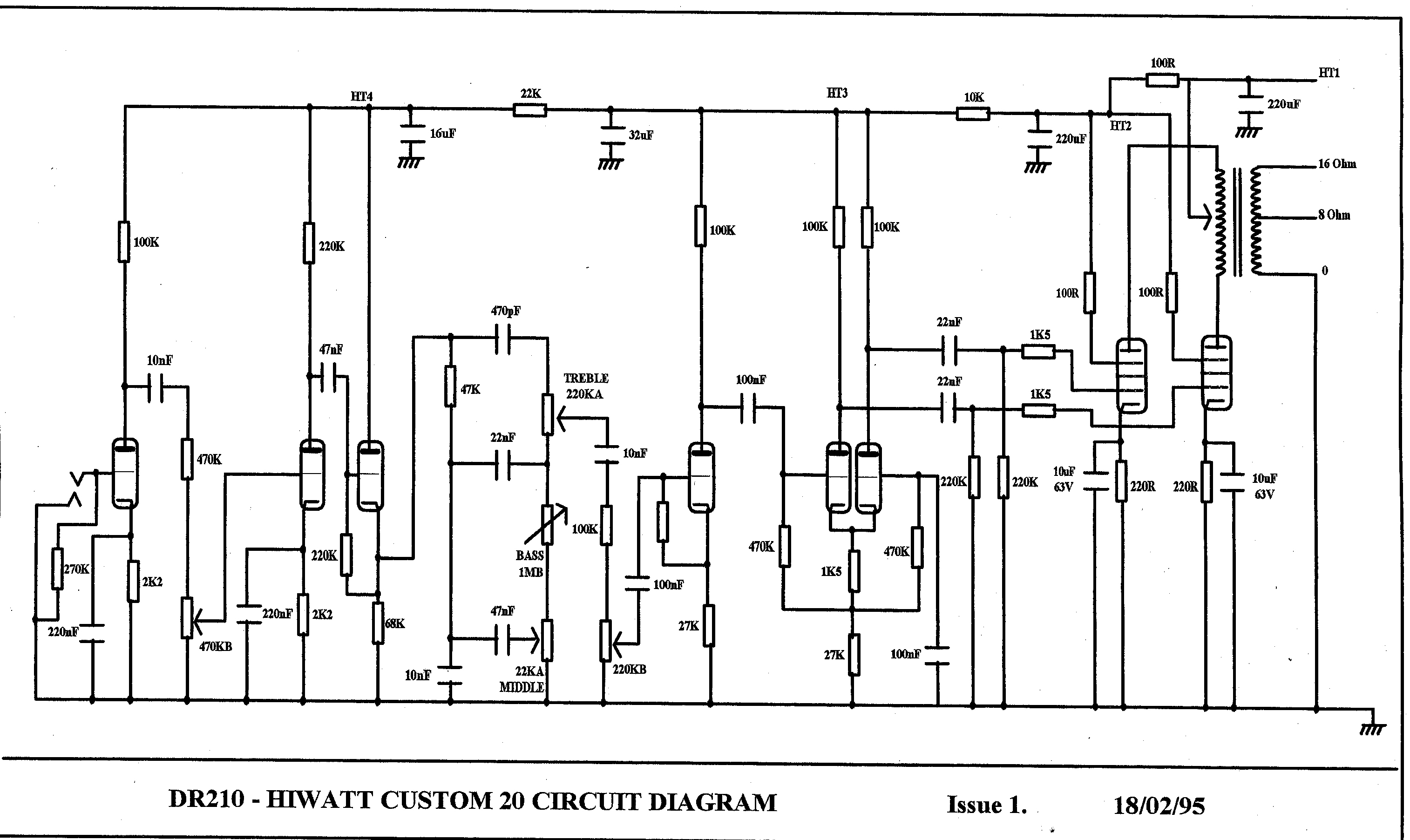
- SA210 Combo Issue 1, 18/02/95
Hiwatt Tech Page
Main Hiwatt Page