A Two-Input Hiwatt Mod
Updated March 2021
During the late 70s, the final evolution of the Hylight Hiwatt preamp was produced. These amps are easily distinguished by the fact they have two input jacks (vs. the four of the earlier models).
Now, I really hate to second-guess Dave Reeves, but the distortion on some of these units when the input volume is turned to maximum sounds really spitty and unpleasant to my ears, particularly on the Normal channel (listen to the examples below.) I did some research when I had one of these models in the shop for some work and discovered what was causing this effect.
The problem is called blocking distortion, and is caused when a self-biased vacuum tube stage is capacitively coupled to the previous stage, and heavily overdriven. In the stock two-input amps, the output of the first stages go to the input volume controls, and from there directly to the input grid of stage two. When the input volume is at maximum, the coupling cap from stage one is pretty much directly connected to the input grids of stage two.
Note: This description and mod applies only to "normal" turret board two-input amps. The PCB two-input amps are likely candidates as well, but the images below won't match, of course. The later "OL" and "OVERDRIVE" amps produced by Biacrown do not need this mod, as they sort of already have it.
Here's an audio demonstration of the sound of blocking distortion on both channels. Note that the master volume setting doesn't really matter as far as this effect is concerned. Note also that the effect is much more pronounced on the Normal channel, because it has a larger coupling capacitor.
Technical Decription of the Problem
(You can skip this section if you just want to do the mod.)
There is a good (but output-stage-centric) description of this problem on Randall Aiken's pages, but the problem paraphrased in preamp-centric form is this:
- Preamp stages are almost always biased in class A, i.e., they conduct current for the entire waveform and the output signal is a (larger) close replica of the input signal. To do this, the stage is typically self-biased via a cathode resistor. This arrangement keeps the grid negative with respect to the cathode during normal operation. At idle, the grid is at zero volts, and the cathode is at 1.5 to 2 volts.
- The R-C coupling normally used between stages tends to zero-balance the input waveform, i.e., the waveform is centered top-to-bottom around the normal idle bias level, and goes above and below zero, but with a mean level of zero.
- The grid of a tube normally presents a very high impedance load to the driving source when it is biased in this manner. When the tube grid bias voltage nears zero, or goes positive with respect to the cathode, its input impedance drops drastically, and it starts drawing current from the source. It behaves similarly to a forward biased diode at that point.
- The forward biased diode clamps the tops of the grid waveform to a relatively fixed point. Since the previous stage is R-C coupled to the grid, the tops are fixed at the clamp point and the entire waveform then shifts downward as signal level is increased, pushing the stage heavily into class B, with a resultant increase in distortion.
- Because the time constant of the R-C coupling is large enough in this case, a transient distortion known as blocking occurs. This happens when the transient signal quickly pushes the clamped grid waveform down far into the cutoff region, and there is a finite time that is required for the grid waveform to recover and float back up to the correct bias point once the transient signal is removed. The input stage is still "centering" the signal, but the new center is much lower than the original, and mean level goes negative (as much as -14 volts in my tests). Until the bias comes back to the correct point, the second stage is effectively cut off for a major portion of the signal (effective class C operation). This results in an un-musical choppy, "fizzy" sounding distortion.
Solutions
During my investigations, I noticed that I could completely cut off the second stage for close to a second by just smacking muted guitar strings, when using the Normal channel!
The way to reduce this problem is to (1) reduce the size of the coupling cap, (2) reduce the shunt grid resistance, or (3) add a large series resistor in front of the grid, which limits the amount of "forward biased diode" current that can flow. (Note that the Bright channel has a much smaller coupling cap, and therefore the problem is not as bad on that channel.)
Changing the coupling caps would certainly change the sound of the amp, so I wanted to avoid that approach. The volume controls are already a low-ish 470k, and I didn't want to have to change them out anyway. Therefore, I decided to just implement the series 470k grid resistor mixer, as was done on the early 70s amps.
WARNING: I'm sure you realize this already. but modifying a vintage amp is considered a crime in some circles, and may reduce its resale value. On the other hand, it might increase it. ;)
The Modification
(1) Remove the nut (and lug if present) on the V2 socket mounting screw clostest to the inputs, and replace it with a two-terminal tag strip (or a three-terminal strip if one lug is grounded, as is the case here).
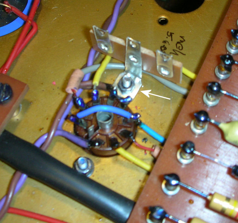
(2) Unsolder the two coax cables from V2 pins 2 and 7, and connect them each to an end terminal on the tag board.
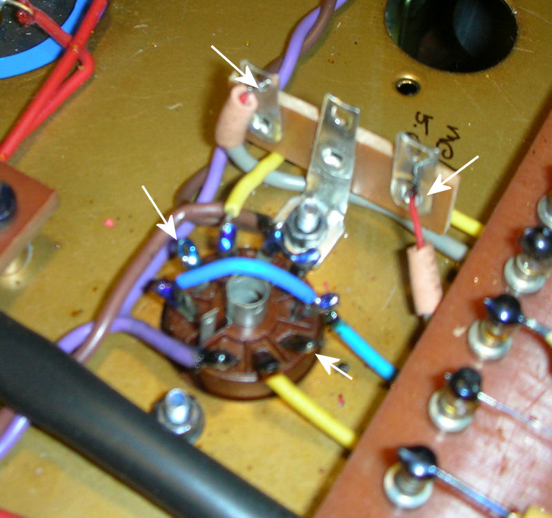
(3) Carefully cut out the wire connecting pin 1 to pin 6 of V2, making sure not to disturb the second wire on pin 6 that goes under the turret board. (This wire is typically blue or sometimes orange)
(4) Connect a 470k resistor from each terminal to pin 7 of V2:
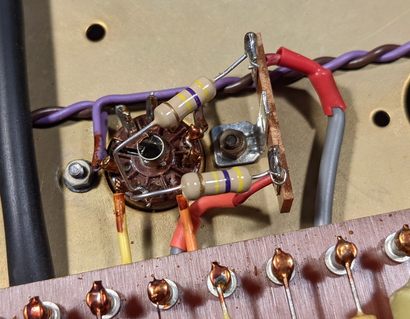
That's all there is to it!
Thanks to JR and MC for the use of their amps!
Hiwatt Tech Page
Main Hiwatt Page